Getting Started with the X100 Source Measure Unit (Legacy)

The X100 (now discontinued, see X200 Source Measure Unit instead) is a powerful and versatile device. The tutorials and demos on this page are intended to help get you started with the X100 and make device characterisation as easy as possible.
To complement this guide, we've also created a range of standard programs to do some of the most commonly required data collection processes. All the programs are based on LabVIEW but are available as stand-alone installs so you don't need to own a copy of LabVIEW to run them (it will install the LabVIEW run time engine automatically). Of course, if you do have a copy of LabVIEW then you can also download the VI (code) and modify it however you see fit.
Contents
- Getting Started with the X100
- Using the Demo-Code to Perform Device Sweeps (Video)
- Programing the X100 (Advanced)
- How to Talk to the X100
- Command List
- LabVIEW Driver Installation
- Basic Commands in Labview
- J-V Sweep in Labview
- Using MatLab with the X100
- Using Python with the X100
- Using Java with the X100
- Xtralien Scientific Python
- Communicating With The X100 with Xtralien Scientific Python
- Xtralien Scientific Python X100 Settings
- Taking Measurements with Xtralien Scientific Python
- Current-Voltage Sweeps with Xtralien Scientific Python
- Upgrading to the Ossila Source Measure Unit (X200)
Source Measure Unit

Getting Started with the X100
The X100 is simple to get up and running. In most cases, it should only take a few minutes!
Plug-in and power-up
The demo code and front panels we've created will in many cases be able to identify your X100 automatically. However, it's useful to know how to do this manually in case the software is unable to do so. All you need to know before starting to code is how to contact a particular device (think of this as the address to which we want to post our commands to).
Identifying your COM port when connected to a Windows computer via USB
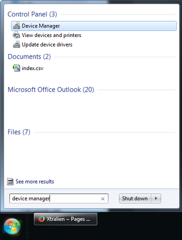
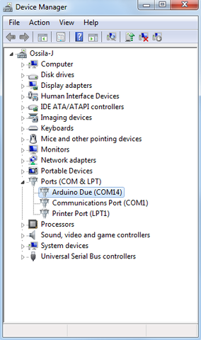
To identify the X100 on Windows simply type Device Manager into the start bar and select the Device Manager program (left image). This brings up a window where you can view all the devices connected to your computer. The X100 should appear under Ports and is labelled as an Arduino DUE as it is based upon the open source Arduino movement. Next to it in brackets will be the COM port number (in this case COM14).
Identifying your IP address when connected to a network
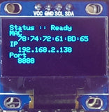
If you're using the ethernet to communicate with the X100 then this is even simpler - when the ethernet cable is plugged in the X100 will automatically detect and identify the network and register itself within a few seconds. The IP address will then be shown on the display such as in the below image (in this case 192.168.2.138):
For most networks the X100 will need no further work - simply plug in and wait a couple of seconds and via the magic of DHCP everything just works and is ready to go. However, there are two examples where this may not work:
- Some large corporate networks (such as universities) have increased security levels and will only allow "known/registered" devices onto the network. If this is the case for your network you will need to register the MAC address first. After this the X100 should be allowed on the network and will just work as normally via DHCP (again fully autmatically from this point with no intervention). Many institutions have their own registration systems for computers and printers and usually have online instructions on how to register a device. The X100 displays the MAC address on startup (as in the above image); this is the key identifier that will allow you to register it on your system.
- If you are using a network with static IP addresses and without DHCP support (rather an old fashioned configuration) then you will need to manually set the IP address. You can do this by first connecting the X100 to your computer using USB before plugging it into the network.
Configuring the X100 Source Measure Unit (Video)
In this video we demonstrate how to configure the X100 source measure unit (SMU) and digital multimeter (DMM), including how to change the screen position, change the current sense range of the SMUs, switch off the display (for use in dark environments) and reset the system.
X100 Front Panel software
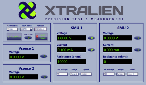
The X100 Front Panel allows you to use the board in the same way as a traditional sourcemeter. You can download the LabVIEW files in a .zip format from our downloads page (note: The code is for LabVIEW versions 11 and later).
The X100 provides two source-measure units, two voltmeters and a shutter control. Once the corresponding hardware ports have been connected, each component can be turned on and off with the buttons next to the displays.
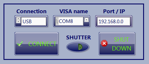
Connection Controls
You can communicate with the X100 via USB or Ethernet connection. Use these controls to choose a connection type and input the appropriate information. Before connection, most of the panel will be disabled and will only become enabled upon successful connection with the board.
Connection: Choose the connection type that you will be using to control the board.
VISA name: If Using a USB connection, the appropriate COM port must be chosen. The COM port for the X100 will be automatically assigned via the operating system.
Port / IP: If connecting via Ethernet, you must type in the board's IP address. When the board is connected to a network, its IP address will be displayed on the built in display.
CONNECT: Once the connection type and address have been chosen, press CONNECT to talk to the board. If a connection is made, the Xtralien logo will change from red to green as shown in the above image.
SHUT DOWN: You can shut the program down at any time with this button.
SHUTTER: The shutter can be turned off and on with this button once the board has connected.
SMU Controls
The source-measure unit can be adjusted to change the range and speed of your measurements.
Set Voltage: Set the voltage output of the SMU.
Range: The range must be set by moving the range header on the board itself, as shown in this video. The software must also be updated, so that the hardware range and software range are synchronised.
Speed: This controls the number of samples taken per point and the measurement frequency. Values are displayed within the drop-down menu.

Using the Demo-Code to Perform Device Sweeps (Video)
This video demonstrates using the X100 source measure unit (SMU channels) to perform basic sweeps of three common types of devices - a resistor, a light emitting diode (LED) and a photodiode. Note this video does not contain sound.
You can download the LabVIEW files in a .zip format from our downloads page (note: The code is for LabVIEW versions 11 and later).
How to Talk to the X100
We've designed the X100 to be simple to use even if you can't program. Many experiments can be done by using the software front-panel or example programs without any further modification. However, for users wishing to develop new experiments and applications, or to integrate the X100 with other instruments, our system is truly versatile.
Which programming languages can I use?
Xtralien has been designed to be simple to use and work with pretty much every programming language (at least anything that supports either serial coms or ethernet, which is pretty much everything commonly in use). Common languages that can be used to interface to it are:
- LabVIEW™
- MATLAB®
- Python
- VB
- Java and Javascript
- Fortran
- C / C++
- Perl
We provide reference code showing basic functionality for LabVIEW™, Matlab® and Python and pseudo-code that can be translated into most other programming languages, so no matter what your favourite language is, you should be up and running quickly.
In order to make it as simple to program as possible we've made the X100 a "text-in text-out" system. You send it a command in a text string and it will send back the result in a text string. We've also made the commands as simple as possible so most of them should be self-explanatory (see the command list here).
Example command and data strings
If you want to send the most basic command to the X100 you can send the string "CLOI Hello" to the X100 and the X100 will then respond "Hello World". This is a useful command to check that the X100 is powered up and fully connected. For reference CLOI stands for Command Language for Open Instruments and is what handles all of the X100 communications (think of it as the X100's brain).
Text sent: "CLOI Hello"
Text received: "Hello World"
It doesn't matter what sentence case you use (e.g. "CLOI hello", "cloi hello" and CLoi HEllO"), they will all be understood as CLOI first converts everything to lower case.
If you want to collect some data, for example to do a sweep on the SMU1 output (source measure unit 1) between -1 and +1 volts in 0.1 volt increments, you should send X100 the text string:
"SMU1 sweep -1 +1 0.1"
The X100 will then perform the sweep and send the data back as a standard formatted text array such as:
"[-1,-1.00000E-03;-0.9,-9.00000E-04;-0.8,-8.00000E-04;-0.7,-7.00000E-04;-0.6,-6.00000E-04;-0.5,-5.00000E-04;-0.4,-4.00000E-04;-0.3,-3.00000E-04;-0.2,-2.00000E-04;-0.1,-1.00000E-04;0,0.00000E+00;0.1,1.00000E-04;0.2,2.00000E-04;0.3,3.00000E-04;0.4,4.00000E-04;0.5,5.00000E-04;0.6,6.00000E-04;0.7,7.00000E-04;0.8,8.00000E-04;0.9,9.00000E-04;1,1.00000E-03;]"
OK, so this doesn't look particularly readable. However, if we understand how it is formatted it's actually very straightforward.
What the X100 is sending us are the readings it has taken from -1 volt to plus 1 V as an array. To represent an array as a string, the standard scientific-computing way to do this is to separate the columns using commas "," and to separate the rows by semicolons ";" while enclosing the whole array in square brackets to make it easy to identify.
Therefore, if we wanted to represent an array of two columns and n rows we could do this as below:
Text representation:
[R1C1, R1C2; R2C1, R2C2;... RnC1, RnC2;]
Actual array:
R1C1 R1C2 R2C1 R2C2 ... RnC1 RnC2
If we go back and look at the text that the X100 sent back we can see that it is actually just sending back a two column array - the first column is the voltage and the second is the current - so the data sent was:
| Voltage (V) | Current (A) |
|---|---|
| -1 | -1.00000E-03 |
| -0.9 | -9.00000E-04 |
| -0.8 | -8.00000E-04 |
| -0.7 | -7.00000E-04 |
| -0.6 | -6.00000E-04 |
| -0.5 | -5.00000E-04 |
| -0.4 | -4.00000E-04 |
| -0.3 | -3.00000E-04 |
| -0.2 | -2.00000E-04 |
| -0.1 | -1.00000E-04 |
| 0 | 0.00000E+00 |
| 0.1 | 1.00000E-04 |
| 0.2 | 2.00000E-04 |
| 0.3 | 3.00000E-04 |
| 0.4 | 4.00000E-04 |
| 0.5 | 5.00000E-04 |
| 0.6 | 6.00000E-04 |
| 0.7 | 7.00000E-04 |
| 0.8 | 8.00000E-04 |
| 0.9 | 9.00000E-04 |
| 1 | 1.00000E-03 |
All measurement data is returned in in scientific notation in volts or amps (rather than microvolts or milliamps) and for those who want specifics, the format specifier is a standard C notation of %8g.
Standard Format Specifier for Data: %8g
How do I send and receive text from the X100
In order to send or receive text from the X100, you need to open a connection to it called a "port" in computing terms. Think of a port as being like a phone line - you need to pick up the phone and dial a specific number before you can talk to someone. The same is true for ports; you need to open a port before you can send any data (text in our case).
You can connect to the X100 using either a USB cable or via ethernet (internet) with instructions on how to identify the ports. The exact method you use to open a port (dial up the X100) depends on the programming language, operating system and connection method, and we have put some examples below (see plugging in a switching on to see how to find out your ports on Windows).
| Operating System | Interface | Example Port Name |
|---|---|---|
| Windows | USB | COM3 |
| Mac | USB | /dev/cu.usbmodem1411 |
| Linux | USB | /dev/tty23 |
| Any OS | Ethernet |
192.168.1.38:8888 i.e. IP address 192.168.1.38 on port number 8888 |
The demo code for LabVIEW™, Matlab® and Python shows how to actually make a connection in these specific languages. For other languages standard communications should work fine, with the only thing you need to know is the IP address (for ethernet) and com port and settings for USB:
USB com port settings (note these are standard default settings) :
* Note that we see good communications from Python at 10 MBit, but typically connect from Matlab or LabVIEW at 920KBit.8 bits, with one stop bit, no parity and auto baud rate up to 10 Mbits*
Example Pseudo-code
The below example represents a generic programming language to explain how you would communicate with Xtralien. For real code examples in LabVIEW, Matlab and Python see the relevant pages.
#Open a USB serial interface to the instrument (on COM1) at a baud rate
#of 115,200 and call that instrument interface X100.
X100=serial(COM1, 920000);
#send a command to the instrument interface named X100. There are lots of
#commands available but one of the most simple and powerful is the sweep
#command. Let's tell the source-measure unit 1 (SMU1) to take a sweep between
# -1 V and 1 V in 0.01V increments as we might do for a photovoltaic device.
print(X100, "SMU1 sweep -1 1 0.1");
#Now read back a line from the instrument interface
data_string=getline(X100);
#You now have your sweep data stored as an array of text in the
#variable called data_string. From here you could save it to disk as a csv file
#to open in a spreadsheet or email it to the far side of the world. However,
#often we'll want to plot it or do some maths on it so its often useful to
#convert it to an array of numbers (instead of text that represents numbers)
#but this is easy since X100 uses standard number and array formatting.
#Data comes back from the X100 in an array in the form
#voltage_1,current_1; voltage_2,current_2; ... voltage_n, current_n;
#Convert data_string into a matrix array by scanning it for pairs of regular
#formatted (%g) numbers separated by a comma. In the case here we have 21 data
#points (from -1 V to +1 V in 0.1 V steps) so we need to repeat this 21 times.
JV_matrix=scantext(data_string,"%g,%g;",21)
#and that's it. We can now plot the data or take a fourier transform or do
#anything we like - the possibilities are endless.
Command List
| Command | Result |
|---|---|
| cloi hello | Returns a 'Hello World' string |
| smu[1,2] set voltage [value] | Sets a voltage |
| smu[1,2] set osr [1-9] | Sets the OSR mode (speed) |
| smu[1,2] measure | Measures current and voltage |
| smu[1,2] measurei | Measures current |
| smu[1,2] measurev | Measures voltage |
| smu[1,2] oneshot [value] | Takes a single current-voltage measurement at a specified voltage |
| smu[1,2] sweep [start] [increment] [end] | Performs a current-voltage sweep |
| smu[1,2] sweep [start] [increment] [end] d | Performs a current-voltage sweep forwards and backwards |
| smu[1,2] get voltage | Returns the voltage last given by the user |
| smu[1,2] get osr | Returns the OSR last given by the user |
| vsense[1,2] measure | Returns a measured voltage, note that at Open Circuit the value returned will be incorrect. |
Xtralien X100 LabVIEW Driver Installation
We have developed several LabVIEW virtual instruments (VIs) for use with the Xtralien X100 Source Meter. These can are available to download from our software downloads pag and can be installed as instrument drivers for easy access while coding. Included are VIs for connecting to the board, changing settings and taking measurements.
Installation Instructions
- Download the above file and extract it. The files are inside a folder names 'Xtralien X100'.
- 2. Make sure LabVIEW is closed.
- 2. Locate the 'instr.lib' folder within the LabVIEW installation folder (e.g. Program Files\National Instruments\LabVIEW 2014\instr.lib).
- 3. Insert the 'Xtralien X100' folder here.
- 4. Start LabVIEW and locate the instrument drivers in Functions -> Instrument I/O -> Instrument Drivers -> Xtralien X100.
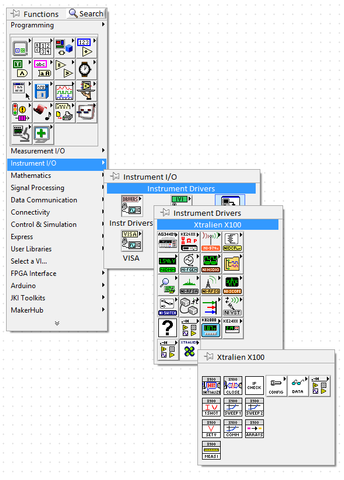
- Start coding with the Xtralien X100!
Basic Commands in Labview
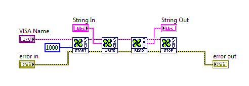
In this section, we will build a simple virtual instrument (VI) that allows us to send commands to the X100 board and receive information from it in return. The image below shows what the code will look like by the end of the tutorial. Both USB and Ethernet can be used to communicate with the board and the commands are the same for each. For the purposes of this tutorial however, we will be only using the USB connection.
The code will involve four processes: START, WRITE, READ and STOP. These are all separated in to their own sub-VIs to keep the code neat and tidy. Splitting code in to smaller VIs is good practice in LabVIEW, as it will allow people to read the code at a glance and keep large programs clear. A connection to the Xtralien is initialised in the START VI. We then WRITE a command to the board in the form of a string. Some of the commands we send such as ‘cloi hello’ will prompt the Xtralien to send us a response string. These are READ and then we STOP the connection with the board.
Programs
All VIs used in this section are available to download as a .zip file.
START VI
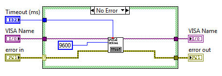
This simple virtual instrument (VI) initialises the serial port connection Xtralien. The VISA serial VI can be accessed via the VISA menu in a LabVIEW block diagram. Timeout, VISA name and error in are all inputs and can be wired up in the main VI shown above. We then output the VISA name and error to allow them to be used by the next program in the flow.
WRITE VI
The string we typed is sent to the Xtralien board by this VI. As before, the VISA name and error are both inputs and outputs.

READ VI
The READ VI is slightly bigger than the previous two programs. The length of the returned string will vary depending on the command we send to the board and some commands such as a very high accuracy 'sweep' can take several seconds to complete. Because of this, we cannot simply send one read command to the board and be sure to receive all the data that we should. Instead, the READ VI continuously tries to read in a string from the Xtralien board until there is nothing left to read. The VISA read tool will output an error if there is no string to read. We can use this error output to continuously test for the presence of a string. Once a the board has completed its task and sent its string, the errors will stop and the VI will start reading. We continue to read in the data until we receive another error, indicating that the Xtralien board has finished sending us data.
Stage 1 - Before Reading
When the VISA read function returns an error, the error is cleaned ready for the next loop, as shown below.

Stage 2 - During Reading
As soon as the Xtralien board begins to send a string, the VISA read function will stop returning an error and the string is stored in a shift register. For a large string, the program will not read the entirety of it during a single loop. Every while loop iteration will therefore read a new section of the string until the program has read the whole thing. These sections are concatenated to rebuild the original string sent by the Xtralien board.

Once the whole string has been read, the buffer will be empty and the VISA read function will return an error again. This returns the program to Stage 1. Using the 'Implies' and 'NOT' functions, we can create a system that will stop the program at this point. The 'Implies' function return False when the top wire is True and the bottom wire is False, with all other cases will returning False. We can use this and a shift register to detect when the VISA read returns True during one loop and False during the next, indicating that it has finished reading the string. We then use a 'NOT' function so that the program will only stop with this condition instead of stopping with any other condition.
Once the while loop has been stopped, the output string is sent back to the main program.
STOP VI
Once the program has read in a string, we want to end communication with the Xtralien board. We use the VISA close function to do this in a simple way as shown below. If an error occurred during the main program, this is displayed in a pop-up dialogue box before the program shuts down. We also flush the board's buffer at this point.

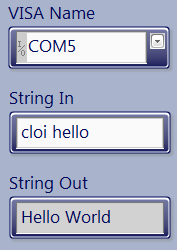
Combining these steps we can create the block diagram shown at the beginning of this section. We should end up with two front panel inputs as shown below; we send a 'cloi hello' command and receive a 'Hello World' string.
A J-V Sweep in LabVIEW
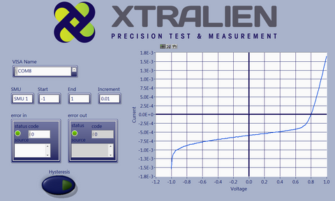
In this section, we will build on the VI we made previously (above) to perform a current-voltage sweep using the Ossila Source Measure Unit. The image below shows what the final VI will look like. We will only focus on the new components in this tutorial, as the START, WRITE, READ and STOP sub-VIs were all explained previously.
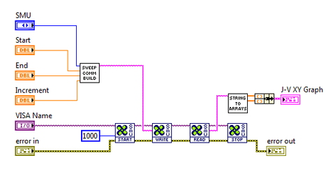
We have taken the Basic Commands program and combined it with two new sub-VIs to create a functional J-V sweep. The two new components are 'Sweep Command Builder' and 'String To Array'.
Sweep Command Builder
The Xtralien board accepts commands in the form of a string. When we know that we are going to be sending a particular command repeatedly, it is easier to automate this process rather than manually typing in every time. This program will be using the 'sweep' command, which works in the format below.
smu[1,2] sweep [start voltage] [voltage increment] [end voltage] [hysteresis]
Where hysteresis is set to 'd' to perform an extra sweep in reverse, or left blank for normal operation. This is useful when a J-V sweep in one direction gives a different result than a J-V sweep in the opposite direction, such as when characterising perovskite solar cells.
An example string would be:
'smu1 sweep -1 0.1 1'
which will use SMU 1 to measure current at specific voltages from -1V to 1V in increments of 0.1V. The important inputs in this program are therefore SMU number, start voltage, voltage increment and end voltage. As you can see in the image above, these are all wired in to the 'Sweep Command Builder' sub-VI.
Below shows the block diagram and front panel of this sub-VI.
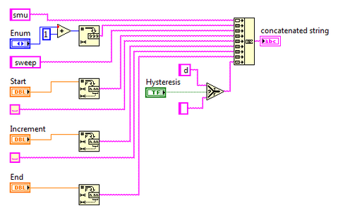
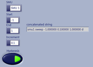
The inputs for SMU number, start voltage, voltage increment, end voltage and hysteresis are all concatenated with the appropriate command strings into a full command.
String To Array
Upon completing a sweep measurement, the Xtralien board will return the results in the form of a long string. It will be enclosed by square brackets and use the format:
[voltage1, current1; voltage2, current2; voltage3, current3]
where current and voltage are separated by a comma, and each measurement is separated by a semi colon. We must be aware of the string's format before we can extract useful data from it. Below shows a the String To Array sub-VI, which we use to transform the returned string into two numerical arrays of voltage and current.
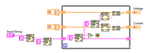
The program first uses a pattern recognition function to remove the square brackets from the string, leaving the numbers in the format:
[voltage1, current1; voltage2, current2; voltage3, current3]
The string then enters a while loop which separates the string in to individual current and voltage measurements by cutting it every time it encounters a semi colon. The pattern recognition function then separates this single measurement into current and voltage values by cutting it at the comma.
The loop will run until the the end of the string, extracting current and voltage from a single measurement during each loop and storing them in arrays. Once the arrays have been output by the Array to String sub-VI, they can be plotted on an XY graph.
Conclusion
In this tutorial we have modified the Basic Commands VI to perform a current-voltage sweep, extracted the current and voltage values and stored them in two separate arrays.
Using Matlab With The Xtralien X100
You can communicate with your X100 board using either USB or ethernet. In the code examples here we primarily use USB as this is available to every copy of MATLAB and will work on most versions from 2008 onwards. Please note that to interface MATLAB to X100 using the ethernet interface will require the instrument control toolbox (in order to access the tcpip function).
In order to talk to the X100 we use a simple set of human readable commands - typically sending a command and then waiting for a response. This command language is called CLOI (Command Language for Ossila Instruments). This has been designed to be as intuitive as possible so that most CLOI commands should do what they say and be easy to understand.
Helper Functions
In order to make life easier we've created some little helper functions to handle the communications between MATLAB and the X100. In order to use them you just need to put them in the same directory as your MATLAB script (for advanced users you can also put them in a separate directory and add that directory to the MATLAB path using the addpath function).
Getting started - The Helper Functions:
The below basic helper functions allow you to start making a wide array of programs. For a full list and description of helper functions click here.
You can download a zip file with the helper functions in here (version 0.91)
| Function Name | Actions |
|---|---|
| OpenCLOI | Open an interface to a CLOI instrument (i.e. the X100 board) |
| SMU1 | Set the voltage on source measure unit 1 (SMU1) and measure the current |
| SMU2 | Set the voltage on source measure unit 2 (SMU2) and measure the current |
| CloseCLOI | Close the interface to a CLOI instrument (i.e. the X100 board) |
Identifying your X100 COM port or IP address
To start communicating to the X100 you need to know the COM port number if you are using USB or the IP address if you are using Ethernet/Internet. If you aren't familiar with this you can find out how to identify the X100 COM port and IP address in the intro section of this page.
Getting going - some basic programs
So you've got the helper functions unzipped and you want to start coding. No problem - it's very straight forward. Here's some example programs. If you're new to programming the green lines are comments and aren't required - they're just there to explain everything.
Program 1 - output a voltage and measure a current.
This is about the simplest program it's possible to make. It's just three lines long (plus a load of comments to explain what we're doing) and sets the voltage and measures the current on SMU1.
%I generally like to start any script by clearing all current variables and
%closing all plots and files and interfaces - i.e. just starting with a
%clean slate:
clear all
clear global
close all
clc
%we also need to add the directory for the helper functions so Matlab
%knows where to find them(this could be anywhere you want but is usually in
%a subdirectory of this demo code. You only actually need to do this once
%per computer but it doesn harm to leave it in either.
addpath('./HelperFunctions')
%Open an interface to Xtralien using the OpenCLOI command.
%All we need to know is the COM port number (in this case COM3 but you can
%identify it by using Device Manager on Windows.
%The OpenCLOI function returns an instrument identifier which in this case
%we'll call Xtralien1 (if we had another instrument connected at the same
%time we could call that Xtralien2).
Xtralien1=OpenCLOI('COM3');
%first of all let specify what measurement range we're using.
%Range Max Current Accuracy
%1 100 mA 10 µA
%2 10 mA 1 µA
%3 1 mA 100 nA
%4 100 µA 10 nA
%5 10 µA 1 nA
%IMPORTANT NOTE:
%The range on the Xtralien needs to be set in hardware as well as software
%by using the small switches (see website or user manual).
SetRange(Xtralien1,'SMU1', 1) %Here we'll use range 1 on SMU1
%We also want to specify the measurement speed (slower=more accurate).
%You can specify an OSR rate from 1 (fastest) to 9 (slowest)
SetOSR(Xtralien1,'SMU1', 5);
%Turn the SMU on (X200 only)
SetEnabled(Xtralien1,'SMU1', 1);
%Now lets set the voltage on SMU1 to 1 volt and measure the current
%We do this by calling the SMU1 command which needs to know which
%instrument it is talking to (in this case Xtralien1) and what voltage to
%set (in this case 1 volt).
[V,I]=SMU1(Xtralien1,1);
%After it has set the voltage on SMU1, it returns the measured voltage as V
%and the measured current as I. Note that in most cases the set voltage and
%the measured voltage should be the same. However, in some cases (such as
%if the device you're trying to measure is short circuited) there could be
%a difference.
%Turn the SMU off (X200 only)
SetEnabled(Xtralien1,'SMU1', 0);
%Now that we've finished our measurement we can close the interface. CloseCLOI(Xtralien1);
%That's it. Our first measurement taken.
Program 2 - Now to do something useful.
Now to do something useful. Lets write a current voltage sweep (also called and IV sweep or JV sweep) which is used for a wide array of devices (diodes, LEDs, OLEDs, etc).
%Open a CLOI interface to the Xtralien board using COM and call it Xtralien1
Xtralien1=OpenCLOI('COM3');
%first of all let specify what measurement range we're using.
%Range Max Current Accuracy
%1 100 mA 10 µA
%2 10 mA 1 µA
%3 1 mA 100 nA
%4 100 µA 10 nA
%5 10 µA 1 nA
%IMPORTANT NOTE:
%The range on the Xtralien needs to be set in hardware as well as software
%by using the small switches (see website or user manual).
SetRange(Xtralien1,'SMU1', 1) %Here we'll use range 1 on SMU1
%We also want to specify the measurement speed (slower=more accurate).
%You can specify an OSR rate from 1 (fastest) to 9 (slowest)
SetOSR(Xtralien1,'SMU1', 5);
%Now lets loop through some voltages. Here we're going to use the matlab
%syntax start:step:stop to create a sweep from -1 Volts to +1 volts in 0.1
%volt (100 mV) steps.
for set_voltage=-1:0.1:1
%for each voltage that we loop through we'll use the SMU1 command to
%apply the desired set_voltage and then measure the actual voltage (V)
%and current (I).
[V,I]=SMU1(Xtralien1,set_voltage);
%Now lets plot the data points so we can see what's happening. Note
%that we put the hold on so that we don't lose one data point when we
%plot the next.
plot(V,I,'X'); hold on;
%We can also display th data in the main matlab command widow if we want.
disp([V,I]);
end
%Now that we've finished our measurement we can close the interface.
%However, before we do it's always good practice to set the voltages back
%to zero again.
[V,I]=SMU1(Xtralien1,0); %set the voltage back to zero
%Turn the SMU off (X200 only)
SetEnabled(Xtralien1,'SMU1', 0);CloseCLOI(Xtralien1); %and close the interfaceNote that in this case we are taking a sweep point-by-point and that instead of using the "for" loop we could just use the SMU1_sweep command (see below example) which would take less programming and make the measurement quicker. However, there are a great many cases where being able to control a sweep directly is very useful as we'll see later on in example 4.
Program 3 - Performing a sweep in a slightly more advanced way
In this program we collect exactly the same data as for program 2 but do it in a more advanced and efficient way. Rather than looping through the voltages using a "for" loop and then collecting and returning a single data point at a time, we use the X100 in-built sweep function to collect everything at one time and return it in one go. It's collects and returns the data more quickly and also makes the code simpler. However, there's always a down side and that is it becomes slightly less versatile.
%Open a CLOI interface to the Xtralien board using COM and call it Xtralien1
Xtralien1=OpenCLOI('COM3');
%first of all let specify what measurement range we're using.
%Range Max Current Accuracy
%1 100 mA 10 µA
%2 10 mA 1 µA
%3 1 mA 100 nA
%4 100 µA 10 nA
%5 10 µA 1 nA
%IMPORTANT NOTE:
%The range on the Xtralien needs to be set in hardware as well as software
%by using the small switches (see website or user manual).
SetRange(Xtralien1,'SMU1', 1) %Here we'll use range 1 on SMU1
%We also want to specify the measurement speed (slower=more accurate).
%You can specify an OSR rate from 1 (fastest) to 9 (slowest)
SetOSR(Xtralien1,'SMU1', 5);
%Now lets run a sweep using Xtraliens in-built sweep function. This time we
%don't need to do a for loop we just use the SMU1_sweep function. In this
%case we're going to sweep from -1 volt in 0.1 volt incriments to +1 volt.
%Note that we have the option of either performing a single or double
%sweep. A single sweep just goes from the start to stop voltage but a
%double sweep then does the same in reverse and sweeps back to the start
%voltage again. This is often useful for measuring hysterises in real
%devices.
[V,I]=SMU1_sweep(Xtralien1, -1,0.1,1,'single');
%Note that in this case V and I are now arrays of data rather than single
%data points (each with 21 rows and 1 column in this case).
%And again we can display in the main window
disp([V,I]);
%and plot on screen
plot(V,I);
%Now that we've finished our measurement we can close the interface.
%As usual lets set the voltages back to zero again first though.
[Vx,Ix]=SMU1(Xtralien1,0); %set the voltage back to zero
CloseCLOI(Xtralien1); %and close the interface
The same type of dual-SMU code can be used for a wide variety of devices such as transistors and sensors.
Using Python With The Xtralien X100
This tutorial gives an introduction to controlling the Xtralien X100 using Python and assumes a working knowledge of basic Python usage, including how to install Python packages onto your system.
Communicating with the X100
When communicating with the X100 board over either USB or Network connection, the most important thing to remember is that everything is simply an ASCII string so you can easily read and interpret the communications.
If you want to connect to the X100 board over USB you would be best using the PySerial module, which you can install through pip or easy_install.
Life is even easier if you would prefer to connect over the network connection as all you will need is already provided along with Python in the form of the socket library.
If you simply want to just get up and start then you can also simply install the xtralien python module, as it will install all of the tools you might want to easily connect.
For beginners to Python we recommend using the library to communicate with the Xtralien X100 because it will help you get started without having to worry about any format-specific issues.
Using the Library
Firstly, install the libraries by running one of the following commands.
$ pip install xtralienor, if you have installed Anaconda
$ conda install xtralienAfter this you should be able to use the xtralien module to find and command all of the boards in your network at once. This is possible using a simple script, like below.
# import the library
import xtralien
# Create a connection to the device
device = xtralien.Device('COM1')

# Print hello world
print(device.cloi.hello())
This should print a list of all the CLOI-based devices available on the network. If this doesn't work, or if you are on a large network it may be better to simply add a device manually. The xtralien library defines some classes that encapsulate additional helper functions so that you, as a user have to worry about less, such as converting the strings to the correct encoding.
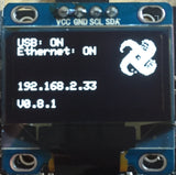
An example of this is below, using the example of a device located at 192.168.2.33, like you can see in the image.
# import the library
import xtralien
# Create the device, with a socket connection
device = xtralien.Device("192.168.2.33", 8888)
# send a command to test the device works
response = device.command("cloi hello", wait=True)
# print the response, which should be "Hello World"
print(response)
Using a network connection
Connecting over a network connection is nice and easy using the socket library. All you need to do is create a TCP connection to port 8888 on the IP address of the board.

An example of this might be 192.168.2.33, like seen above, in which case you should be connecting using a command like below.
# Import the required library
import socket
# Create the initial socket
connection = socket.socket()
# Connect the local socket to the one on the board
connection.connect(("192.168.2.33", 8888))
# Send a "cloi hello" command
connection.send("cloi hello")
# Make sure that we got "Hello World!" back
response = connection.recv(576)
if response == "Hello World\n":
print("Success")
else:
print("Not an xtralien board")
Using the above code you should be able to connect to an xtralien board at 192.168.2.33 on port 8888, and if you see Success printed out on the screen then you have sent a CLOI command, well done.
Using a serial connection
Python provides no serial library by defualt, so you can install PySerial instead, which is community-provided code under the Python Software Foundation License, which is an Open-Source approved license.
To install PySerial simply run
$ pip install pyserialor if you run Anaconda on your system run
$ conda install pyserialUsing it is almost as simple as using the built-in socket library, with the addition of having to know which serial port you need to select.
# Import the required library
import serial
# Create a Serial Connection on COMX (where X is the port)
# Note: This will be different on different platforms,
# the one shown is Microsoft Windows
connection = serial.Serial('COMX')
# Send a "cloi hello" command
connection.write(b"cloi hello")
# Read the response
response = connection.read(12)
if response == b"Hello World\n":
print("Success")
else:
print("Not an xtralien board")
The above code will connect to the serial/COM port COMX and test the board to make sure it is an xtralien board. If everything is plugged in and connected then running the above code you can check if you are using the correct COM port.
Using Java With The Xtralien X100
Java is one of the most popular Programming languages to use as it offers a simple introduction to many programming concepts. Because of this, we have created a Java Module to enable a simple start into using Java to control the X100.
Connecting to the X100 is essentially the same as in any other language, and as such will consist of a Socket connection to the X100. This is available as a built-in class as java.net.Socket.
To import all of the libraries that we will need to connect to, and communicate with the X100, add the following lines to the top of your Java file.
import java.lang.*;
import java.io.*;
import java.net.*;
The rest of the code that we will be using to communicate with can be seen below for completeness, particularly as it is a short class.
class X100 {
private String address;
private Socket socket;
private BufferedReader reader;
private BufferedWriter writer;
public X100(String address) {
this.address = address;
try {
this.socket = new Socket(this.address, 8888);
this.reader = new BufferedReader(new InputStreamReader(this.socket.getInputStream()));
this.writer = new BufferedWriter(new OutputStreamWriter(this.socket.getOutputStream()));
}
catch (UnknownHostException e) {
System.out.println("Could not find host");
}
catch (IOException e) {
System.out.println("Error occured with IO");
}
}
public String command(String command) {
return this.command(command, false);
}
public String command(String command, boolean wait) {
try {
this.writer.write(command, 0, command.length());
this.writer.flush();
char[] cbuf = new char[512];
while (wait && !this.reader.ready()) {}
Thread.sleep(1);
this.reader.read(cbuf, 0, 512);
return new String(cbuf);
}
catch (IOException e) {
System.out.println("IO Exception");
return "";
}
catch (InterruptedException e) {
System.out.println("Interruped");
return "";
}
}
public static void main(String[] args) {
X100 x = new X100("192.168.2.237");
System.out.println(x.command("cloi hello\n", true));
x.command("set range 2");
System.out.println(x.command("smu1 measure\n", true));
}
}
The above class provides a very simple interface to the X100 through the Java Socket class, which at it's core is a simple TCP connection over Ethernet. In this example we also make use of Buffered readers and writers to enable easy reading and writing from the connection streams. This choice will also make it easier to add other methods of communication at a later stage by allowing the creation to only occur once, and allow all reading and writing to be the same.
When using the Socket class you need to supply both a host (either the name or IP address of a device) and a port for the connection to connect to. You will then have access to both input and output streams on which to communicate over. For this we will be using the BufferedReader and BufferedWriter classes as they are provided with Java and are well supported.
When using the BufferedWriter class we can easily send commands over the connection by calling the method BufferedWriter.write(data), which will add the data data to connection buffer. A call to BufferedWriter.flush() will then actually send the buffered data down the stream to the X100.
The inverse is also possible, you can easily read using the BufferedReader, although you will first need to create an empty character array to transfer the data into.
Using the above class, it is trivial to send commands and receive responses from the X100 by using the X100.command(command, wait_for_data) method. The String command provided is sent to the X100 and then if wait_for_data is true then the function will pause until data is ready, after which point the data will be read into a buffer and returned as a String.
Xtralien Scientific Python
Communicating With The X100 with Xtralien Scientific Python
You can communicate with the Xtralien X100 via either USB or Ethernet connections. This tutorial will show you how to use the Xtralien Scientific Python software to talk to your X100.
USB Connection
Manually Setting a COM Port
When an X100 is connected to a PC, it is assigned a specific 'COM' port. This can be found using the 'Getting Started' section of this page.
Once you know the correct COM port, you can connect to an X100 via the following command:
from xtralien import *
Device1 = X100.USB('COM1')
We name the connection Device1, though this can be named anything you like. This example uses COM1 as the port name.
In order to test this connection, we can send a simple command to the board:
from xtralien import *
Device1 = X100.USB('COM1') print(Device1.cloi.hello())
The cloi hello command should return a 'Hello World' string if there is a working connection.
Automatically Setting a COM Port
serial_ports() function, which returns a list of open COM ports. As discussed in our list tutorial, using a [0] returns the first item in a list. This code will therefore return the first open COM port.from xtralien import *
COM = serial_ports()[0]
Device1 = X100.USB(COM)
print(Device1.cloi.hello())
Ethernet Connection
Manually Setting An IP Address
As with the USB connection, we need to find the board's address in order to connect to it. To determine the IP address of an X100, please use the 'Plug In and Switch On' guide.
Once you know what the address is, you can use the following code to connect:
Device1 = X100.Network('192.168.2.150')
print(Device1.cloi.hello())
where '192.168.2.150' is an example address.
Automatically Setting An IP Address
As with the COM ports in the previous section, you can search for X100 IP addresses automatically. The X100.discover() function searches the network for boards and returns their addresses in a list format. This can be used instead of the Network() function to connect to a board like this:
from xtralien import *
Device1 = X100.discover()[0]
print(Device1.cloi.hello())
Here we use the first address in the list by using [0] after discover().
Staying Connected
If a board becomes disconnected, the program will error and the COM port will not close as it should. To solve this problem, we use the with command:
#For USB
from xtralien import *
COM=serial_ports()[0]
with X100.USB(COM) as Device1:
print(Device1.cloi.hello())
#For Ethernet
from xtralien import *
with X100.discover()[0] as Device1:
print(Device1.cloi.hello())
Notice that the print command is indented relative to the with. The indented code will run until it completes, or the connection is lost. The program will then close the connection and continue running.
Xtralien Scientific Python X100 Settings
The Xtralien X100 has several programmable settings with which a measurement can be customised. This tutorial will explain these settings and show you how to change them using Xtralien Scientific Python.
The sample code for this tutorial is displayed below.
from xtralien import *

### 1.Board Settings ###
precision = 3
### 2. SMU Settings ###
#SMU1#
range1 = 2
osr1 = 5
unsafe1 = True
##SMU2#
range2 = 2
osr2 = 5
unsafe2 = True
### 3. Update Board Settings ###
with X100.USB('COM11') as Dev1: # Connect to the Device via USB
Dev1.cloi.set.precision(precision, response=False) # Set Precision for both SMUs
Dev1.smu1.set.range(range1, response=False) # Set SMU1 range
Dev1.smu1.set.osr(osr1, response=False) # Set SMU1 OSR
Dev1.smu1.set.unsafe(unsafe1, response=False) # Set SMU1 unsafe
Dev1.smu2.set.range(range2, response=False) # Set SMU2 range
Dev1.smu2.set.osr(osr2, response=False) # Set SMU2 OSR
Dev1.smu2.set.unsafe(unsafe2, response=False) # Set SMU2 unsafe
Connecting To The X100
We can connect to an X100 over USB using the code:
with X100.USB('COM11') as Dev1: # Connect to the Device via USB
This is explained in our tutorial on communicating with the X100. We can also communicate with the X100 over Ethernet.
Precision
Precision determines the significant figures of measurements. For example, a precision of 3 would return a measurement of 1.2345 as 1.23. Setting a board precision limits the amount of raw data returned by the board, however this data can also be manipulated within a script after a measurement has taken place.
You can set the precision using the following code:
Dev1.cloi.set.precision(precision,response=False)
Range
There are five ranges on the X100, each with a different maximum current and resolution. These can be seen in the following table:
| Range | Resolution | Burden | Noise |
| ± 100 mA | 100 µA | < 10 mV | 6.0 E-6 |
| ± 10 mA | 10 µA | < 10 mV | 6.0 E-7 |
| ± 1 mA | 1 µA | < 10 mV | 6.0 E-8 |
| ± 100 µA | 100 nA | < 10 mV | 6.0 E-9 |
| ± 10 µA | 10 nA | < 10 mV | 6.0 E-10 |
You can set the range using the following code:
Dev1.smu1.set.range(range1, response=False)
where smu1 is the smu number (smu1 or smu2) and range1 is a variable.
OSR
OSR (Sample Rate) determines the number of samples that the X100 takes during each individual measurement. The greater the OSR, the more accurate the measurement and the longer a measurement takes to perform. Set a value between 1 (fast, low accuracy) and 9 (slow, high accuracy).
You can set the OSR using the following code:
Dev1.smu1.set.osr(osr1, response=False)
where smu1 is the smu number (smu1 or smu2) and osr1 is a variable.
Unsafe
The board has a current limit by default, meaning that it will not increase in voltage once a certain current value has been reached. This check takes processing time however, therefore it can sometimes be advantages to turn it off. Setting unsafe to True will turn off this safety check.
You can set unsafe to off using the following code:
Dev1.smu1.set.unsafe(unsafe1, response=False)
where smu1 is the smu number (smu1 or smu2) and unsafe is a variable (True or False).
Taking Measurements with Xtralien Scientific Python
There are several ways of performing measurements using the the Xtralien X100 Source Measure Unit (discontinued). In Xtralien Scientific Python, we use four basic commands: measurei, measurev,measure and oneshot.
Example Code
This example code demonstrates the use of all four measurement commands:
from xtralien import *

### 1. Connect ###
with X100.USB('COM12') as Dev1: # Connect to the Device via USB
 ### 2. Turn on SMU (X200 only) ###
Dev1.smu1.set.enabled(1, response=0)[0] # Turn SMU on
 ### 3. Measure Current ###
measuredi = Dev1.smu1.measurei()[0] # Take a current measurement
print('Measured Current is ',measuredi,' A')
 ### 4. Measure Voltage ###
measuredv = Dev1.smu1.measurev()[0] # Take a Voltage measurement
print('Measured Voltage is ',measuredv,' V')
 ### 5. Measure Voltage and Current ###
vandi = Dev1.smu1.measure()[0] # Take a measurement of both voltage and current
print('Measured Voltage and Current are ',vandi[0], ' and ',vandi[1])
 ### 6. Set Voltage, Measure Voltage and Current ###
vandi = Dev1.smu1.oneshot(2)[0] # Take a measurement of both voltage and current
print('Measured Voltage and Current are ',vandi[0], ' and ',vandi[1])
This code prints the result:
Measured Current is 1.57e-06 A
Measured Voltage is 0.00 V
Measured Voltage and Current are 0.00 and 1.64e-06
Measured Voltage and Current are 2.00 and 1.49e-06
Code Breakdown
1. Connect
with X100.USB('COM1') as Dev1: # Connect to the Device via USB
Here we connect to an Xtralien X100 over USB, using COM port 1. This process is covered in our tutorial on Communicating With The X100.
2. Turn on SMU (X200 Only)
Dev1.smu1.set.enabled(1, response=0)Our latest Source Measure Unit (the X200) allows the user to turn the SMUs on and off. This means that we need to turn the SMU on before we can take measurements.
-
Dev1is the name that we gave to the X100 in section 1. -
smu1determines which of the two on-board source measure units (SMUs) we want to measure.
3. measurei (Measure Current)
 current = Dev1.smu1.measurei()[0] # Take a current measurement
print('Measured Current is ',current,' A')
-
measureitells the board to take a current measurement and return a string in the scientific notation format. This string is within a list with only one entry. - We use
[0]to change the number from a list format to a double.
We create a variable named current and assign the measured value to it. We then use the print command to display it along with some text
4. measurev (Measure Voltage)
 voltage = Dev1.smu1.measurev()[0] # Take a Voltage measurement
print('Measured Voltage is ',voltage,' V')
This is similar process to the measurei command, only this time we are measuring voltage using the measurev command.
5. measure (Measure Voltage and Current)
 vandi = Dev1.smu1.measure()[0] # Take a measurement of both current and voltage
print('Measured Voltage and Current are ',vandi[0], ' and ',vandi[1])
Here we use the measure command without specifying i or v. This will take a measurement of both and return them in a list. To split the voltage and current values, we index the list using [0] for the first value and [1] for the second.
6. oneshot (Set Voltage, Measure Voltage and Current)
 vandi = Dev1.smu1.oneshot(2)[0] # Take a measurement of both voltage and current
print('Measured Voltage and Current are ',vandi[0], ' and ',vandi[1])
The oneshot command works in a similar way to the measure command, wherein both the voltage and current are returned. This command allows you to set a voltage at which to perform a measurement. The oneshot(2) command tells the X100 to output 2 V and measure the voltage and current. We then split these values from the returned list as explained in the section above.
Current-Voltage Sweeps with Xtralien Scientific Python
A current-voltage (IV) sweep is a common measurement used to characterise semiconductor devices, such as photovoltaics (PVs) or light emitting diodes (LEDs). This tutorial will show you how to perform an IV sweep measurement using Xtralien Scientific Python and an Xtralien X100 Source Measure Unit (SMU).
An IV sweep is a series of measurements from one voltage to another, with several steps in between. The voltage choice will depend on the materials used and the device type that is being tested. For instance, a perovskite solar cell typically requires an IV sweep from 0 V to 1 V.
The full code is shown below. Download the IV Sweep Python Script here.
from xtralien import *

### 1.Sweep Settings ###
vstart = 0 #Starting Voltage (V)
vend = 1 #End Voltage (V)
vstep = 0.1 #Step Size (V)
smu = 'SMU1'
### 2.Create Variables ###
vnum = ((vend-vstart)/vstep) + 1 #Calculate number of steps in sweep
volts = linspace(vstart,vend,vnum) #Create voltage list

### 3. Perform Sweep ###
with X100.USB('COM1') as Dev1: #Connect to the Device via USB
results = vstack([Dev1[smu].oneshot(v) for v in volts]) #Create array of oneshots
print(results) # Print results
We will now break down the code and discuss what is happening in more detail.
1. Sweep Settings
Here we choose the settings of our sweep. This program only requires four choices to be made: starting voltage (vstart), end voltage (vend), voltage step size (vstep) and smu choice (smu).
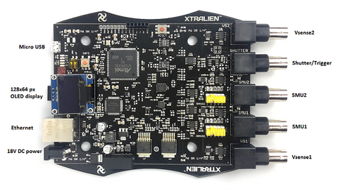
The smu is either 'SMU1' or 'SMU2', depending on which source the device is connected to. The SMUs are labelled in the diagram below.
2. Create Variables
Calculate Measurement Number
The number of measurements (vnum) we take depends on the settings given in section 1. This can be determined by dividing the voltage range (vend - vstart) by (vstep).
In this example, the calculation would give (1 - 0) / (0.1) = 10.
A list of 10 values between 0 and 10 would give:
[ 0.00, 0.111, 0.222, 0.333, 0.444, 0.556, 0.667, 0.778, 0.889, 1.00 ]
Notice that the step size is 0.111 instead of the 0.1 that we wanted. This is because the vnum calculation gives a value of 10, even though we really need 11 steps between 0 and 10. To solve this problem, we use vnum+1 instead. This gives us the list we wanted:
[ 0.0, 0.1, 0.2, 0.3, 0.4, 0.5, 0.6, 0.7, 0.8, 0.9, 1.0]
Creating A Voltage List Using Linspace
The numpy linspace function creates a linear list of numbers. The arguments are (start number, end number, total numbers). For instance, linspace(0,50,6) would create this list:
[0, 10, 20, 30, 40 ,50]
We use this to create a list of voltages that we would like to apply during our sweep.
In this example, volts = linspace(vstart,vend,vnum) would create the list:
[ 0.0, 0.1, 0.2, 0.3, 0.4, 0.5, 0.6, 0.7, 0.8, 0.9, 1.0]
For more information on lists, see our python list tutorial.
3. Perform Sweep
Connecting To The X100
This section is where the commands are sent to the X100 and data is received. First we must establish a connection with the board using with and the USB method. These are discussed in a previous section of this page.
Taking Measurements
The measurement commands for the X100 are explained in our Taking Measurements Tutorial.
The oneshot function sets a voltage of v and measures the voltage and current through the device. We use this and our list of voltages to perform the sweep.
Dev1[smu].oneshot(v) tells Dev1 to perform a single oneshot measurement on the chosen smu using voltage v.
A oneshot command returns data in the format [[voltage,current ]].
The vstack command combines a series of arrays into a single, vertically stacked array. We can use this and a for loop to create an array of our measurements.
Combining these concepts, we create the line:
results = vstack([Dev1[smu].oneshot(v) for v in volts])Printing The Array
Now that we have stored our sweep data in an array, we can simple use the print command to display the results.
Considering An Upgrade?
The X100 Source Measure Unit has been discontinued and replaced with the Ossila Source Measure Unit (X200).Take a look at these resources to see if the Source Measure Unit is suitable for your needs.
Source Measure Unit

 Measuring Solar Cells with a Source Measure Unit
Source measure units are vital pieces of equipment used for many applications, including the measurement of new solar cells.A small-scale test device is usually used to characterize the solar cell efficiency. These devices are too small to generate usable power but allow you to test the design. Exposing the cell to a known amount of light power, using a solar simulator, allows you to calculate the electrical power produced per unit area.
Read more... Source Measure Unit: Python Programming Guide
Semiconductors are a material with properties that fall between a good conductor (like metals) and a good insulator (like rubber). Depending on the conditions, semiconductors can be conductive or insulating. This ability to control the flow of electrical current in modern electrical devices, such as microchips and photovoltaics.
Read more...