
Connecting the Micromanipulator to the Source Measure Unit
Precise electrical characterization of small-scale devices may require meticulous connections between micromanipulator probes and an source measure unit (SMU). While the Ossila Source Measure Unit excels in biasing devices and measuring currents, integrating the SMA-connectorized micromanipulator with BNC-connectorized SMU can present challenges.
There are several key factors to consider for successful integration, including the number of device terminals, safety interlocks, electromagnetic interference (EMI) shielding, grounding requirements, line resistance compensation, and overall measurement performance.
We will delve into practical considerations for a basic two-terminal device measurement and discuss advanced techniques such as Kelvin connections and the use of triaxial cables for improved measurement sensitivity and EMI rejection.
When working with electrical measurement setups, particularly those involving SMA-to-BNC connections, safety is of the utmost importance. There are several things to consider which can help you balance safety and sensitivity in your characterization measurements: ensuring proper grounding and shielding, implementing short circuit protection and using isolation transformers.
Connections for Basic I-V Measurement
This fundamental experiment is used for characterizing two-terminal devices, such as diodes, using micromanipulated probes and a source measure unit. By applying a voltage sweep across the device and measuring the resulting current, you can measure key electronic characteristics. To do this you will need 2 Ossila Micromanipulators: one to contact the anode (positive terminal) and the other to contact the cathode (negative terminal).
To establish the electrical connection, the central pin of the BNC "SMU1" connector should be connected to the anode probe, while the outer shield of the BNC connector should be connected to the cathode probe. This configures the SMU to source the voltage to the anode and measure the current flowing through the device.
Crucially, the shields of both SMA cables connected to the micromanipulators must be connected to the BNC cable shield. This establishes a common ground reference and provides essential EMI shielding. This connection can be made manually using the circuit shown below.

Advanced n-channel MOSFET Measurement
An n-channel field-effect transistor (n-channel MOSFET) acts like a voltage-controlled switch. It's a three-terminal device with a gate, source, and drain. By applying a voltage (Vgs) to the gate, you can control the current (Ids) flowing between the source and drain.
For testing this three-terminal device, you'll need three probes and a dual-channel SMU.
The Ossila Source Measure Unit can simultaneously sweep both the gate-source voltage (VGS) and drain-source voltage (VDS) for this measurement (see example uses of source measure units).
Similar to the basic I-V measurement, the probe SMA cables need to connect to the BNC connectors on the SMU. The interface for this setup can be built according to the diagram below.


Electromagnetic Interference
To characterize small-scale devices, you must carefully consider the effects of electromagnetic interference (EMI). External electromagnetic fields, generated by various sources such as digital circuits, communication systems, and even ambient radio waves, can induce unwanted currents and voltages within the measurement setup, corrupting the data. This is particularly critical in sensitive measurements involving small currents or high impedance devices.
Unshielded probe tips, which are directly exposed to the environment, act as antennas, readily picking up ambient electromagnetic noise. Furthermore, if the Device Under Test (DUT) itself is not adequately shielded, it can act as a receiving antenna, further amplifying the impact of EMI. Effective shielding strategies that can mitigate these effects include:
- Using a grounded Faraday cage to enclose the entire test setup, including probes, DUT, and connections. This provides a robust barrier against external electromagnetic fields.
- Coaxial cables offer a degree of shielding by enclosing the signal-carrying conductor within a grounded braided shield. For highly sensitive measurements, triaxial cables offer superior performance. Triaxial cables incorporate a second, inner shield (often referred to as the "guard" conductor) in addition to the outer shield (or "common"). This provides enhanced isolation for the inner core (“force” or “sense”) and significantly reduces the impact of common-mode noise.
- Proper grounding practices. Ground loops, formed by imperfect ground connections, can introduce significant noise into the measurement system.
- Careful routing of cables and minimizing their exposure to potential noise sources are also crucial considerations.
By implementing these shielding strategies and employing careful grounding practices, researchers can minimize the impact of EMI and ensure the accuracy and reliability of their electrical measurements.
Coaxial cables

Coaxial cables are essential for transmitting sensitive signals in the presence of EMI. Their design inherently provides a degree of shielding. A coaxial cable consists of a central conductor surrounded by a concentric cylindrical conductor known as the shield conductor. This is typically a braided copper shield. This configuration creates a well-defined transmission line with a characteristic impedance.
The outer shield is a conducting material that, when properly grounded, acts as a Faraday cage confining the electromagnetic fields generated by the inner conductor. This minimizes the coupling of external electromagnetic fields to the signal path, reducing the impact of EMI. Additionally, the coaxial geometry minimizes the radiation of electromagnetic energy from the cable itself, further reducing interference with surrounding circuits.
The characteristic impedance of a coaxial cable is determined by the dimensions and dielectric properties of the cable. Matching the characteristic impedance of the cable to the input and output impedances of the connected devices minimizes signal reflections, ensuring efficient and accurate signal transmission.
Triaxial Cables

For highly sensitive measurements, triaxial (often just “triax”) cables offer significant advantages over conventional coaxial cables. Triaxial cables incorporate an additional conductive braided shield (“common” or “shield”), allowing better EMI shielding from both the core (“force” or “sense”) and inner shield (“guard”).
The additional inner shield significantly improves common-mode noise rejection. By carefully controlling the potentials on the inner and outer shields, common-mode currents can be minimized, leading to significantly improved signal-to-noise ratios. Furthermore, triaxial cables minimize leakage currents, which can significantly impact measurement accuracy in high-impedance or low-current measurements. The inner shield also provides enhanced isolation between the central conductor and the outer shield, improving safety in high-voltage applications.
While triaxial cables offer superior performance, they are generally more expensive and less readily available than coaxial cables. Their use is typically justified in applications where the highest possible measurement sensitivity and noise immunity are critical.
Coaxial to Triaxial Adapters
Many experimental setups will need an interface between coaxial and triaxial devices. This requires the use of specialized adapters. When doing this, users must ensure the proper mapping of conductors between the two cable types.
One common configuration involves connecting the coaxial shield to the triaxial guard (left). This arrangement typically provides the highest sensitivity for low-current measurements. However, it requires significant safety considerations due to the driven guard biasing the coaxial shield.
An alternative configuration connects the coaxial shield to the triaxial shield (right), leaving the triaxial guard floating. This approach simplifies user safety considerations but may result in reduced sensitivity compared to the first configuration.

The optimal adapter configuration depends on the specific requirements of the measurement and the desired balance between sensitivity and safety.
Kelvin Connections
In precise electrical measurements, it is crucial to minimize the impact of lead wire resistance. Lead wire resistance can introduce significant errors, particularly in low-resistance or high-current measurements, due to voltage drops along the current-carrying leads.
Kelvin connections, also known as four-wire sensing, provide an effective solution to this problem. This technique utilizes two sets of leads: one set for current delivery and another set for voltage sensing. The current-carrying leads are connected directly to the DUT at the current injection points. The voltage sensing leads, however, are connected to the DUT at separate points, minimizing the influence of voltage drops along the current-carrying leads.
By measuring the voltage drop across the DUT using the independent voltage sensing leads, the effects of lead wire resistance are effectively eliminated. This technique is particularly critical in high-current applications and in measurements where high accuracy is paramount.
This is the method for eliminating line resistance in 4-wire resistive temperature device (RTD) measurements. It is also used in the Ossila Four Point Probe for making accurate sheet resistance measurements.
Test Enclosure
Enclosing the entire test setup within a conductive enclosure offers several significant advantages.
- EMI Shielding: A properly grounded enclosure provides effective shielding against external electromagnetic interference, minimizing its impact on sensitive measurements.
- User Safety: In high-voltage applications, a grounded enclosure provides an additional layer of safety by containing potential electrical hazards.
- Light Tightness: For light-sensitive devices, an enclosure can effectively block ambient light, ensuring consistent and reliable measurements.
-
Environmental Control: Some applications require control of the ambient temperature, humidity, or atmosphere in which the DUT is operated.
The specific requirements of the test setup will dictate the appropriate enclosure design. For applications utilizing coaxial cables, a simple grounded enclosure is often sufficient. However, when employing triaxial cables with a driven guard, the enclosure itself must be carefully grounded to ensure proper operation and maintain user safety.

Beyond EMI shielding and user safety, the test enclosure can also contribute to environmental control. By incorporating features such as temperature stabilization and vibration isolation, the enclosure can create a stable and controlled environment for the DUT, improving the accuracy and reproducibility of measurements.
Safety
Working with electrical circuits requires careful attention to safety to prevent electrical shock and equipment damage.
- Voltage Limits: Always operate within safe voltage limits. Refer to local regulations for safe limits relevant to your experimental setup (e.g., the “Extra-low voltage”, below 50 VAC and 75 VDC in the EU). If you intend to operate at high voltages, employ engineering controls and risk management applicable to your local regulations.
- Grounding: Proper grounding is crucial for both safety and accurate measurements. Ensure all equipment, including the SMU, micromanipulators, and test enclosure (if used), are properly grounded to a common ground point.
- Shielding: When connecting triaxial and coaxial cables, exercise caution when connecting the guard. As mentioned earlier, connecting the coaxial shield to the triaxial guard can introduce safety hazards due to the high voltages that may be present on the guard.
- Short Circuit Protection: Implement appropriate short circuit protection measures to safeguard the SMU and the DUT from accidental short circuits. This may involve using fuses or electronic current limiting circuitry.
- Isolation: Use isolation transformers to electrically isolate the measurement setup from the mains power supply, reducing the risk of electrical shock.
- Personal Protective Equipment (PPE): Wear appropriate PPE, such as safety glasses and insulated gloves, when working with high voltages or potentially hazardous circuits.
- Regular Safety Checks: Conduct regular safety checks of all equipment and connections to ensure proper operation and identify any potential hazards.
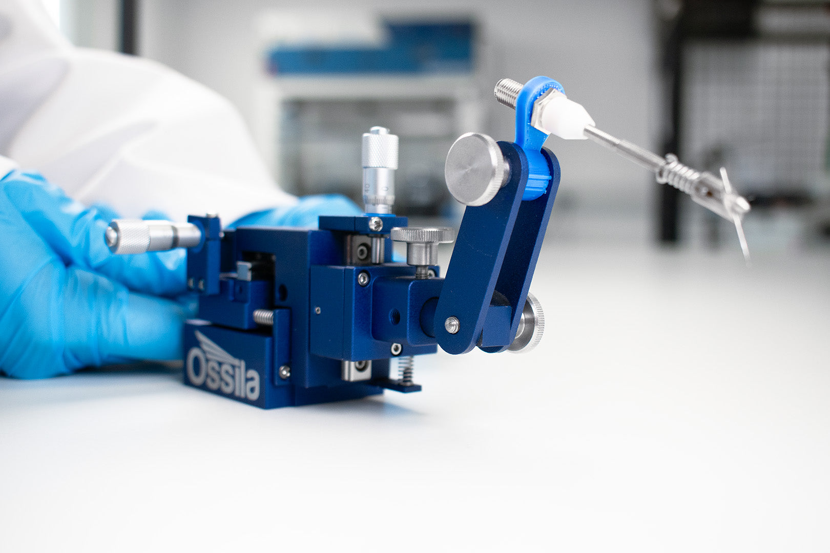
Micromanipulator
Learn More
 How to Position the Ossila Micromanipulator Probe
Learn how to accurately adjust your micromanipulator probe.
Read more... How to Change the Handedness of your Micromanipulator
We have designed the Ossila Micromanipulator to be flexible in case you need to change the handedness of your unit. Follow the steps in this guide.
Read more...Contributors
Written by
Product Developer
Diagrams by
Graphic Designer