OEM Source Measure Unit Set
Lab EquipmentFlexible Solution for OEM Electrical Measurements
Bulk discount for equipment manufacturers
Specifications | Features | Software | Gallery | In the Box | Resources and Support
Designed for scientists and engineers working on the next generation of electronic devices, the Ossila Source Measure Unit is one of our most adaptable and fundamental pieces of equipment. Available as a set of boards for easy incorporation into OEM applications, which includes 5 fully functional SMU PCBs individually packaged in antistatic bags.
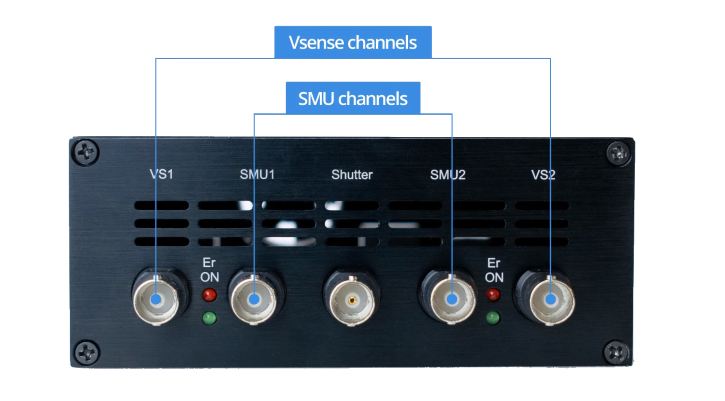
Each source measure unit contains four advanced instruments on a single board: two SMUs (voltage source and current sense) and two precision voltage sense channels. Plus, the general-purpose shutter/trigger enables it to control (or be controlled by) other instruments.
The Ossila SMU has been the foundation for developing some of our industry-leading systems:
- The Four-Point Probe for precise sheet resistance measurement.
- The Solar Cell IV Test System and LED Measurement System for IV curve analysis and characterization.
- The Potentiostat for conducting cyclic voltammetry.
Specifications
Source Measure Units (SMU 1 & SMU 2)
The SMUs output a voltage and then measure both the voltage and current. The output voltage is always measured on the output to the BNC, rather than assuming it is at the set voltage. This is to account for any load effects, for example, short circuiting the output, or low impedance causing a small drop in voltage. Each source measure unit has multiple current ranges, so that you can measure both large and small currents with accuracy.
Voltage Source Specifications
| Range | Accuracy | Precision | Resolution |
|---|---|---|---|
| ±10 V | 10 mV | 333 µV | 170 µV |
Voltage Measure Specifications
| Range | Accuracy | Precision | Resolution |
|---|---|---|---|
| ±10V | 10 mV | 50 µV | 10 µV |
Current Measure Specifications
| Range | Max Current | Accuracy1 | Precision2 | Resolution | Burden |
|---|---|---|---|---|---|
| 1 | ±200 mA | ±500 µA | 10 µA | 1 µA | <20 mV |
| 2 | ±20 mA | ±10 µA | 1 µA | 100 nA | <20 mV |
| 3 | ±2 mA | ±1 µA | 100 nA | 10 nA | <20 mV |
| 4 | ±200 µA | ±100 nA | 10 nA | 1 nA | <20 mV |
| 5 | ±20 µA | ±10 nA | 1 nA | 0.1nA | <20 mV |
1Accuracy has been measured at the maximum current of the range.
2Precision has been measured at the highest OSR (9).
Precision Voltage Meter Specifications (Vsense 1 and Vsense 2)
The voltage meters are designed to accurately sense small voltages while also having a wide dynamic range (±10 V).
| Range | Accuracy | Precision | Resolution |
|---|---|---|---|
| ±10 V | 10 mV | 50 µV | 10 µV |
Shutter/Trigger
The shutter/trigger can be used either as an input or an output. It can be used to send a trigger signal to other instruments or configured to wait for a trigger from other instruments. The voltage level of this BNC is 5 V because any higher may cause damage to the port.

Physical Specifications
| Computer Connectivity | USB-B and Ethernet |
|---|---|
| Measurement Connections | BNC connector |
| Dimensions (W x H x D) | 120.25 mm x 20 mm x 185 mm (4.74" x 0.79" x 7.28") |
| Rail Dimensions (W x H x D) | 5 mm x 1.6 mm x 160 mm (0.2" x 0.06" x 6.3") |
Manuals
OEM Source Measure Unit user manual
OEM source Measure Unit programming documentation
OEM Source Measure Unit Features
Five Independent Channels
Dual source measure and voltmeter functionality: two SMU channels for voltage output while measuring current and/or voltage and two dedicated channels for precise measurement of external voltages. Control and program external instruments with the shutter/trigger channel.
Wide Voltage and Current Range
Select from five distinct current ranges tailored to your experimental requirements, along with 10 speed and resolution settings. Perform measurements at DC or low frequencies across a voltage range of -10 V to +10 V, accommodating current levels from as low as 10 nanoamps (nA) to 200 milliamps (mA).
Choose Your Preferred Programming Language
The system is compatible with a wide range of programming languages, including Python, MATLAB, Java, C/C++, and many others, for seamless integration into your workflow.
Software
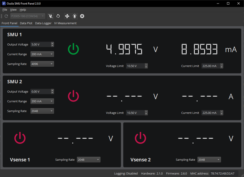
The Ossila Source Measure Unit includes Front Panel software that enables you to start taking measurements as quickly as possible. With the program you can:
- Control each SMU and Vsense channel independently, allowing you to perform many of the most common electrical measurements.
- Set voltage and measure current with two independent SMU channels (voltage source, current sense).
- Quickly and accurately measure voltages with the two Vsense channels.
- Easily set sampling rates for the SMUs and Vsense channels via the interface.
- Save your data as a portable spreadsheet (.csv) file or a text (.txt) file for analysis with your favourite software package.
Programming Languages
The user-friendly design works with almost any programming language. Common languages that can be used to interface to it are:
Software Requirements
| Operating System | Windows 10 or 11 (64-bit) |
|---|---|
| CPU | Dual Core 2 GHz |
| RAM | 4 GB |
| Available Drive Space | 200 MB |
| Connectivity | USB 2.0, or Ethernet (requires DHCP) |

Other Software
We also have software for performing specific measurements with the Ossila Source Measure Unit. These can be downloaded for free from our software and drivers page. The currently available measurements are:
- I-V curves
- Solar cell characterisation and lifetime
- Four-point probe sheet resistance
Source Measure Unit Gallery
In the Box
The standard items included with the Ossila Source Measure Unit are:
- 5 x OEM source measure unit PCB in antistatic bag
- 5 x 24 V / 2 A DC power adapter
- 5 x USB-B cable
- User manual and QC data
- USB drivers and Front Panel software installer
Resources and Support
 Source Measure Unit: Python Programming Guide
The Ossila Source Measure Unit can be controlled directly over USB or Ethernet using various commands. These can be sent as strings, enabling the use of a large variety of programming languages, including Python, MATLAB, LabVIEW, Java, and C/C++.
Read more...


