LED Measurement System
Electrical Characterization, Lab Equipment
Fast and Simple LED Characterization
Perform IVL sweeps, measure current efficiency & power efficiency and track lifetime
Overview | Specifications | Features | Gallery | Software | In the Box | Accessories | Resources and Support
Perform current-voltage-luminance (IVL or JVL) measurements for new LED devices (including OLEDs and QLEDs). The low cost, fully integrated Ossila LED Measurement System has built-in light sensors for illuminance, luminance, and white count measurements. The dedicated software can calculate current efficiency and power efficiency for your LED, and lifetime mode measures performance over time using the constant-voltage method for lifetime assessments, operational stability tests, and stress testing.
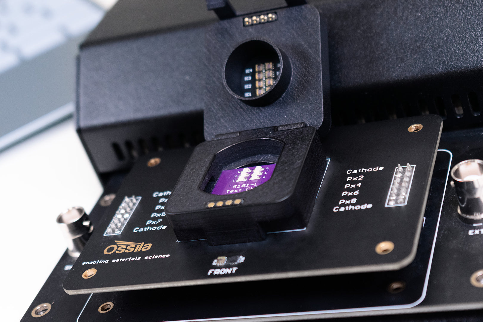
Compatible with the 25 mm2 or 20 mm x 15 mm substrates, test LED devices, find key metrics, and track LED lifetimes with minimal stress.
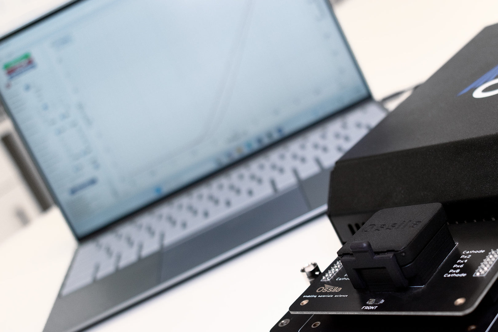
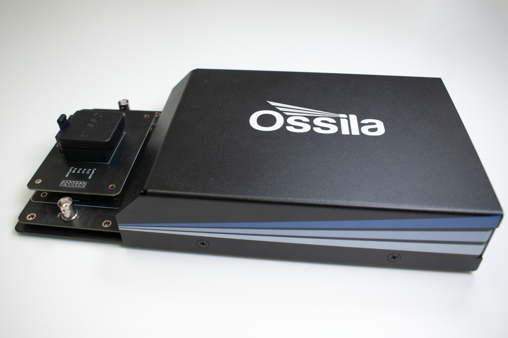
Complete System
Integrated luminance and current measurement
LED Measurement
Efficiency metrics, lifetime, and IVL sweeps
Free Software
For plug-and-play device testing
Specifications
| Wavelength Range | 400 nm – 750 nm (white count only: 400 nm – 1050 nm) |
|---|---|
| Substrate Compatibility | T2005B - S211 (20 x 15 mm, PV and OLED) T2005E - S2006 (25 mm Square, PV and OLED) |
| Overall Dimensions (W x H x D) | 151 mm x 50 mm x 300 mm (9.94" x 1.97" x 11.81") |

Voltage Source Specifications
| Range | Accuracy | Precision | Resolution |
|---|---|---|---|
| ±10 V | ±10 mV | 333 µV | 170 µV |
Voltage Measurement Specifications
| Range | Accuracy | Precision | Resolution |
|---|---|---|---|
| ±10 V | ±10 mV | 50 µV | 10 µV |
Current Measurement Specifications
| Range | Accuracy | Precision | Resolution | Burden |
|---|---|---|---|---|
| ±200 mA | ±500 µA | 10 µA | 1 µA | <20 mV |
| ±20 mA | ±10 µA | 1 µA | 100 nA | <20 mV |
| ±2 mA | ±1 µA | 100 nA | 10 nA | <20 mV |
| ±200 µA | ±100 nA | 10 nA | 1 nA | <20 mV |
| ±20 µA | ±10 nA | 1 nA | 0.1 nA | <20 mV |
Illuminance Measurement Specifications
| Range | Accuracy | Resolution |
|---|---|---|
| 100 klx | ±10% | 1.8432 lx |
| 5000 lx | ±10% | 0.1152 lx |
| 500 lx | ±10% | 0.0144 lx |
LED Measurement System Features
Rapid Characterization
Take current-voltage-luminance measurements with the fast software. The system records illuminance, luminance and white count. To speed up the characterization process, the system will then calculate both the current efficiency and power efficiency of your LED.
One System For LED and Solar Cell Measurement
Maximize lab space and streamline your workflow with a single, versatile system. Intelligent design means the LED Measurement system can be used for Solar Cell I-V testing. Simply swap out the riser board, add an illumination source, and download our our alternative Solar Cell Testing Software.
Easy-To-Use Software
Take a range of measurements with one system: IVL curves, current and power efficiency, constant-voltage lifetime measurements, white count, and illuminance measurements. Create individual setting profiles to quickly and easily repeat measurements and perform similar scans.
Quick and Easy
Plug in the system, install the PC software, and you're ready to go! The Ossila LED Measurement System has been designed by research scientists to address the frustrations associated with measuring and characterizing LEDs. The intuitive interface and clean design make the system simple and easy-to-use.
LED Measurement System Gallery

Looking for the Ossila OLED Lifetime Measurement System?
The LED Measurement System replaces the OLED Lifetime Measurement System. The new device holder and upgraded software package together add support for new characterization measurements, but it is still easy to take OLED lifetime measurements with the LED Measurement System. If you are looking for a manual device, consider the Ossila Source Measure Unit.
Software
The LED current-voltage-luminance measurement is controlled using intuitive and user-friendly PC software. All of the measurements can be fully customized so that you can tailor the software to your experiment.

The software has two measurement tabs: characterization and lifetime. Characterization mode performs I-V measurements of LEDs while measuring the illuminance, luminance, white count, and calculating the current and power efficiencies. The lifetime mode enables you to set a constant voltage and measure the performance of the LED over an extended time.
With the PC software, you can:
- Perform current-voltage-luminance measurements anywhere between -10 and 10 V.
- Take high resolution measurements, with voltage increments as low as 1 mV.
- Manage the experiment more directly, with custom settle times between applying voltage and measuring current.
- Measure illuminance, luminance, white count, current efficiency, and power efficiency using the built-in sensors.
Data is saved to .csv (comma-separated value) files, which are formatted to be easy to read and analyze. Settings are saved along with the data, making it easier to keep a record of parameters you use for each experiment. Additionally, settings profiles can be saved for each different type, so that you can easily perform repeat measurements or use particular configurations.
Software Requirements
| Operating System | Windows 10 or 11 (32-bit or 64-bit) |
|---|---|
| CPU | Dual Core 2 GHz |
| RAM | 2 GB |
| Available Hard Drive Space | 121 MB |
| Monitor Resolution | 1440 x 960 |
| Connectivity | USB 2.0 Ethernet (requires DHCP) |
In the Box
- Ossila LED Measurement System
- USB-B cable
- 24 VDC power adaptor
- USB Driver with QC test data
- LED IVL Software
Accessories and Related Products


Resources and Support
 OLED Testing Guide
This guide gives you an overview of what to consider when characterizing an OLED, as well as tips for their measurement.
Read more...The schematics below show the layout of the substrates along with the available deposition shadow masks. The pixelated anode substrates come with six ITO fingers which define the pixels plus an additional cathode bus-bar.
Read more...