What is Hyperfluorescence?

Hyperfluorescence refers to the light emitted by a device that combines conventional fluorescence with thermally activated delayed fluorescence (TADF) to enhance brightness. Hyperfluorescence organic light-emitting diodes (HF-OLEDs) represent the 4th generation of OLED technology. First published in 2014, HF-OLEDs surpass the previous generations by obtaining high external quantum efficiencies (EQE) and narrowband emission with high color purity. This has made wider color gamut displays accessible suitable for advanced applications such as high-definition televisions, immersive virtual reality systems, and cutting-edge mobile devices.
HF-OLEDs address the broadband limitations of thermally activated delayed fluorescence (TADF) and phosphorescent emitters by utilizing their properties within a multicomponent emissive layer. TADF materials are used as sensitizers alongside separate terminal emitters to access more efficient and narrowband emission. As a result, hyperfluorescence is sometimes referred to as TADF-assisted fluorescence. The key advantages of HF-OLEDs are improved efficiency, color purity, and power consumption.
Key Mechanisms in Hyperfluorescence
Hyperfluorescence (HF) relies on many of the same mechanisms found in earlier-generations of OLED. When charge carriers are injected into the device from the electrodes and reach the emissive layer, they recombine to form either singlet or triplet excitons. Similarly to thermally activated delayed fluorescence (TADF) and phosphorescence, triplet excitons (which account for 75% of all excitons) are harvested through a process called reverse intersystem crossing (RISC). This TADF mechanism enables HF-OLEDs to theoretically achieve 100% efficiency.
The emissive layer within HF-OLEDs can include three different components:
- Host: Efficient at collecting excitons.
- Sensitizer: Specializes in harvesting triplet excitons (sometimes also acts as the host material)
- Terminal emitter: Responsible for producing fast, narrowband light emission.
Since the active layer of HF-OLEDs contains at least three different materials, energy transfer between these components is a critical mechanism. Hyperfluorescence relies on emission from the singlet excited state (S1) to the ground state (S0). This requires Förster Resonance Energy Transfer (FRET), a process that enables energy transfer between singlet excited states of the different materials. By combining triplet state harvesting with efficient FRET to a narrowband fluorescent emitter, hyperfluorescence achieves both high efficiency and excellent color purity.
|
|
Förster Resonance Energy Transfer (FRET)
Förster resonance energy transfer (FRET) is a non-radiative energy transfer process between two neighbouring molecules. In the case of hyperfluorescence, energy is transferred from a sensitizer (donor, typically TADF) to a terminal emitter (acceptor). This is a singlet-singlet transition (S1 --> S1), typically from the lowest singlet state of each molecule.
FRET efficiency within a system can be measured with respect to the Förster radius distance (RF). RF represents the distance between the two molecules where the energy transfer is 50 % efficient. It can be expressed by the following equation:
|
|
The FRET rate can then be determined from the Förster radius, the donor radiative lifetime, and the distance between the donor and acceptor molecules:
|
|
From these equation the key parameters that influence FRET in hyperfluorescence OLEDs are:
- Distance between donor (sensitizer) and acceptor (terminal emitter) - are they close enough for FRET to occur?
- Energy difference between the S1 states of the donor and acceptor molecules.
- Orientation and dihedral angle of the donor and acceptor units in the sensitizer molecules - large effect on oscillator strength and the energy of the S1 state.
- Spectral overlap and emission properties of both donor and acceptor molecules.
- Molecular structure of the sensitizer - avoiding the chance of unfavourable conformers.
Long emission lifetimes and low intersystem crossing rates enhance FRET efficiency. Achieving such prolonged singlet exciton lifetimes requires minimal non-radiative decay rates, ensuring that FRET remains the dominant process. Strategies to optimize FRET include careful molecular engineering or selection:
- Sensitizers with both slow radiative and non-radiative decay rates provide sufficient time for FRET to effectively accumulate and govern exciton dynamics. The efficiency of FRET is further optimized as the sensitizer's excited-state energy is reduced. This is supported by the extended excited-state lifetime, which ensures that the majority of the singlet exciton population remains in the S1 zeroth vibrational level.
- Terminal emitters with S0-->S1 transitions that have high oscillator strength and narrow emission bandwidth are highly effective. Their well-defined and intense spectra create strong spectral overlap with the excited states of sensitizers. This overlap facilitates efficient energy transfer from the sensitizer to the terminal emitter.
Surprisingly, sensitizers with relatively low singlet and triplet excited-state energies can still efficiently transfer energy to terminal emitters. This expands the design possibilities, allowing the use of lower-energy sensitizers and host materials that were previously thought unsuitable. As a result, this approach broadens the range of potential host and emitter combinations, improving flexibility in material selection for advanced optoelectronic applications.
Reverse Intersystem Crossing (RISC)
Reverse intersystem crossing (RISC) plays a role of similar importance in thermally activated delayed fluorescence (TADF), as it is also being actively exploited. This process is crucial for harvesting triplet excitons, ensuring high efficiency. A high kRISC enables the rapid conversion of triplet excitons into singlet excitons, facilitating efficient energy transfer to the fluorescent emitter. The TADF sensitizer holds the responsibility for rapid rates of intersystem crossing.
Inefficient Dexter energy transfer (DET) between the triplet state of the sensitizer and the terminal emitter must be avoided. Therefore, sensitizers are typically designed to ensure full conversion of triplet excitons into singlet excitons. These singlet excitons can then be efficiently transferred to the terminal emitter via FRET, enabling effective delayed fluorescence.
Why Use Hyperfluorescence in OLEDs?
Hyperfluorescence is one of the state-of-the-art OLED technologies, achieving a breakthrough in efficiency, color purity, and cost-effectiveness. Over four generations, OLEDs have evolved significantly, with each iteration addressing the limitations of its predecessors. Below is a table summarizing the key characteristics of these generations:
| 1st Generation | 2nd Generation | 3rd Generation | 4th Generation |
|---|---|---|---|
| Fluorescence | Phosphorescence | TADF | Hyperfluorescence |
|
Low cost High color purity Low efficiency |
High cost Low color purity High efficiency |
Low cost Low color purity High efficiency |
Low cost High color purity High efficiency |
- Fluorescent OLEDs can only harvest singlet state excitons so have poor efficiency.
- Phosphorescent emitters are expensive, with short operational lifetimes as well as poor stability of blue emitters.
- TADF emitters have long triplet exciton lifetimes causing poor stability with broad emission spectrums.
- Hyperfluorescence offers low cost, highly efficient OLED devices with narrowband emision for high color purity.
Material Components for Hyperfluorescence
TADF Sensitizers
The key role of the TADF sensitizers is to ensure efficient triplet exciton harvesting via reverse intersystem crossing (RISC) and the subsequent transfer of the singlet excitons to the fluorescent emitter. Fast RISC reduces the concentration of triplet excitons and triplet-triplet annihilation events in the emissive layer.
TADF emitters typically exhibit broad emission spectra due to varied donor-acceptor (D-A) dihedral angles and contributions from aggregated states in the film. In HF-OLEDs this broadband emission spectra is not an issue as ideally it doesn't contribute to the final emission from the photoactive layer.
Sensitizer requirements:
Reverse intersystem crossing rates are determined by spin-orbit coupling (SOC) and the energy gap between the S1 state and the T1. Enhancing spin-orbit coupling can be done by incorporating different chemistries such as heavy atoms, heteroatoms and aromatic carbonyls. Minimizing the energy gap can be done by separating the electron disribution of transition orbitals involved in S1 by designing molecules with donor and acceptor units. For example, 4CzIPN has been used as a TADF sensitizer in a long-lifetime green-emitting HF-OLED device. Its molecular design features four carbazolyl groups as electron-donating units and cyano groups as electron-accepting units. The high stability of the device was attributed to the inherent stability of 4CzIPN and the spectral overlap between its emission and the MR-TADF emitter ω-DABNA-PH.
Examples of Sensitizers
Terminal Emitters
Fluorescent emitters are chosen or designed to minimize excited-state lifetime by harnessing large oscillator strength. They are also selected for their narrow emission to ensure color purity in HF-OLED devices. The FRET rate is dependent on the energy difference between the two S1 states of the sensitizer and terminal emitter. This can be controlled through molecular engineering such as introducing substituents, rigidification and increased polarity.
To achieve high performance, the electronic state energies of the fluorescent emitters must align well with those of the TADF molecules to enable fast Förster singlet-exciton energy transfer. The doping concentration of the fluorescent emitter in the emissive layer must also be carefully optimized to ensure efficient singlet energy transfer. Additionally, this optimization should minimize undesirable loss mechanisms, such as triplet exciton dissipation through Dexter energy transfer (DET) and direct charge trapping.
Terminal emitter requirements:
Molecular design in regards to terminal emitters has focused on ensuring narrowband emission. First generation fluorescent emitters are used as in the HF-OLED system they are no longer facing issues of inaccessible triplet excitons which are made accessible by the TADF sensitizer. Newer multi-resonance TADF (MR-TADF) materials are also used as their rigidity and frontier molecular orbital distributions lead to extraordinary photophysical properties.
Examples of Terminal Emitters
Host Materials
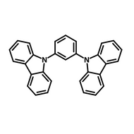
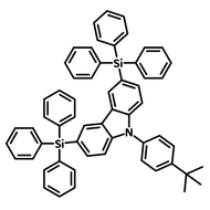
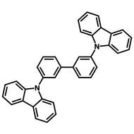
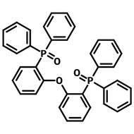
The role of the host is to facilitate rapid charge transfer, typically with little bias to electrons or holes. It needs to provide a stable environment for efficient exciton recombination. One key feature of host materials is to have the highest triplet energy level compared to both the sensitizer and emitter molecules to prevent energy back transfer. The host also dilutes the dopant molecules, reducing aggregation and concentration quenching effects, which helps maintain high photoluminescence efficiency. By providing a non-interfering environment, the host material helps preserve the dopant's intrinsic emission properties, such as narrowband emission for precise color purity.
Host material requirements:
Examples of Host Materials
Example devices
The following table highlights examples of HF-OLED devices, showcasing combinations of sensitizers, terminal emitters, and host materials, along with their performance metrics. The listed parameters include maximum external quantum efficiency (EQEmax), power efficiency (PEmax), and corresponding chromaticity coordinates (CIE), demonstrating the diverse approaches used to optimize device efficiency and color performance:
| Sensitizer | Terminal Emitter | Host | EQEmax/1000 cd m−2 (%) | PEmax/1000 cd m−2 (lm W−1) | CIE | Ref. |
|---|---|---|---|---|---|---|
| ACRSA | TBPe | DPEPO | 13.4/8.7 | 18/7 | (0.17, 0.30) | |
| PXZ-TRZ | TBRb | mCBP | 18.0/17.2 | 58/33 | (0.45, 0.53) | |
| 3BPy-mDTC | C545T | mCBP | 23 | 69.9 | (0.20, 0.56) | |
| TXO-TPA | DBP | mCBP | 16.9/2.6 | 27.8/1.8 | (0.65, 0.35) |
Challenges of Hyperfluorescence
The ultimate challenge when designing a hyperfluorescence OLED device is to avoid triplet exciton formation in the terminal emitter (where they decay non-radiatively). There are two key mechanisms that cause competing loss channels:
- Dexter energy transfer (DET) of triplet excitons
DET loss pathways occur when the triplet state excitons of the sensitizer transfer to the triplet state of the terminal emitter. This can be avoided by molecular engineering to product emitters with a large energy difference between S1 and triplet states.
- Direct charge trapping on the final emitter
A challenge in HF-OLEDs is the formation of intermolecular charge transfer (CT) states, where charges become trapped on the TADF co-host and fluorophore. These states, close in energy to singlet and triplet levels, can cause energy losses by generating triplet states on the fluorophore. Increasing donor-acceptor separation can mitigate this.
These loss mechanisms not only reduce efficiency but also shorten the device's lifespan, as the prolonged presence of triplet states can lead to material degradation. Other energy loss mechanisms include:
- Exciton annihilation
Another form of energy loss is singlet–triplet annihilation (STA). In fluorescent emitters it is a non-radiative process where a singlet exciton (S1) interacts with a triplet exciton (T1), leading to energy loss. This reduces device efficiency in OLEDs, as triplet excitons quench singlet excitons, especially under high exciton density.
- Limitations of host materials
Limited progress has been made in hyperfluorescence host material technology, especially in for blue HF-OLED devices. While it can be optimized to achieve lower driving and turn-on voltages, challenges with solubility and processability remain persistent. One host material may not be enough to manage both terminal emitter and sensitizer requirements. For example, for blue TADF sensitizers high-polar hosts may be required to boost TADF properties. However, this can lead to enhanced charge transfer effects in blue MR-TADF emitters.
Hyperfluorescence Design Principles
The design of hyperfluorescent OLED devices requires careful selection and optimization of components to achieve high efficiency, color purity, and long operational lifetimes. Below are some critical principles to consider:
- Spectral overlapping of sensitizer and terminal emitter: overlap of the emission spectra of the sensitizer with the absorption spectra of the fluorescent emitter is crucial for Forster resonance energy transfer mechanisms. Tuning the spectral overlap is essential for achieving high-quality and efficient emission. Techniques for adjusting this feature include advanced material design, device optimization and simulations.
-
Avoiding Dexter energy transfer (DET): In HF systems, energy loss occurs via DET from the triplet state of the TADF co-host to the final emitter, requiring molecular orbital overlap at short distances. Dexter transfer occurs through direct orbital overlap between the host and emitter, limiting it to the Ångstrom-scale distance. Design principles to prevent DET include:
- Bulky substituents (e.g., tert-butyl or butyl-phenyl) increase intermolecular distance, reduce orbital overlap, and shield active cores.
- Frontier orbital localization on the molecular core, with inert peripheral groups, blocks overlap.
- Triplet upconversion: Enhance reverse intersystem crossing (RISC) by modifying donor groups to strengthen charge transfer and increase the RISC rate constant.
- HOMO–LUMO separation: Use donor-acceptor designs to restrict orbital overlap and suppress triplet transfer, with resonance effects dispersing excitons in the host matrix.
- Covalent encapsulation: functionalization of terminal emitters with insulating alkylene straps reduce intermolecular interactions and as a result aggregated quenching.
- Using MR-TADF Emitters: Multi-resonance TADF molecules, such as ν-DABNA, leverage boron and nitrogen/oxygen atoms to minimize vibronic coupling and reduce the singlet–triplet energy gap. By distributing the frontier molecular orbitals (FMOs) across electron-deficient boron and electron-rich nitrogen atoms within rigid polycyclic aromatic rings, these molecules achieve a small ΔEST, strong oscillator strength, and narrow emission. While they often experience efficiency roll-off at high current densities, this issue is mitigated when they serve as terminal emitters in HF-OLED systems.
- Exciplex-induced stability: A co-host system containing donor and acceptor molecules with exciplex characteristics helps minimize the transfer of electron/holes to the terminal emitter. As a result the carrier or triplet accumulation deteriorates which helps increase the operational device lifetime. As the charge carriers travel in the host, direct charge trapping on the emitter can also be reduced.
- Terminal emitter polarity: The polarity of the fluorescent emitter molecules is important. As the molecules dipole moment (polarity) increases, the trapping increases but direct recombination also decreases. HF-OLEDs with low-polar sensitizers have a small carrier injection barrier and therefore full excitation is possible.
- Terminal emitter orientation: The higher the degree of molecular orientation of the fluorescent emitter, particularly with the dipole moments aligned horizontally relative to the substrate, the light extraction efficiency increases. This alignment directs more emitted light outward, reducing losses from light being trapped within the device or surface plasmon loss. As a result, outcoupling efficiency increases and this directly impacts the external quantum efficiency (EQE) of the HF-OLED:
|
|
OLED Materials

Learn More
Thermally Activated Delayed Fluorescence (TADF) is a mechanism by which triplet state electrons can be harvested to generate fluorescence.
Read more... Multi-Resonance Thermally Activated Delayed Fluorescence (MR-TADF)
Multiple resonance thermally activated delayed fluorescence (MR-TADF) is a light emitting process engaging the same working principle as thermally activated delayed fluorescence (TADF).
Read more...
References
- High-efficiency organic light-emitting diodes with fluorescent emitters, Nakanotani, H. et al., Nature Communications (2014)
- Forthcoming hyperfluorescence display technology: relevant factors to achieve..., Gawale, Y. et al., Frontiers in Chemistry (2023)
- Dual enhancement of electroluminescence efficiency and operational stability..., Furukawa, T. et al., Scientific Reports (2015)
- A quantum dynamics study of the hyperfluorescence mechanism, Giret, Y. et al., J. Mater. Chem. C (2021)
- A perspective on next-generation hyperfluorescent organic light-emitting diodes, Deori, U. et al., Chem. Sci. (2024)
Contributors
Written by
Application Scientist
Diagrams by
Graphic Designer


